The Sound of DIY
I had already made/improved a little portable speaker by reusing the circuit board of an old cheap speaker, pairing it with a better speaker and putting it in a "stylish" (but impractical) wooden case.
But having learnt how to create my own PCBs (with Iron Peroxyde III) I wanted to create my very own speakers to use on my desk. Let me clarify: I wanted a set of speakers that I could use both via cable with my computer and via bluetooth with my phone. The final speaker was supposed to seat on my desk, serving as a screen stand for my main monitor. 🖥️
I already had a pair of old JBL mid-range speakers and I found a TDA-2005 in my garage. All was left to do was to mount everything together!! 🔊
I was far from thinking it was the beginning of a three-year long project...
The Amplifier Circuit
I was really pleased when I saw there were already a couple examples in the TDA-2005 datasheet showing different ways to use it. I settled for a basic circuit using a single IC to drive two speakers.
Iron Peroxyde Age
I designed the circuit using KiCad and made the first board. After testing: it did not work. So I made another one with a couple changes: same result. For my defense, I was stuck with single face PCB so the wiring was not easy and certainly not ideal... 😵💫
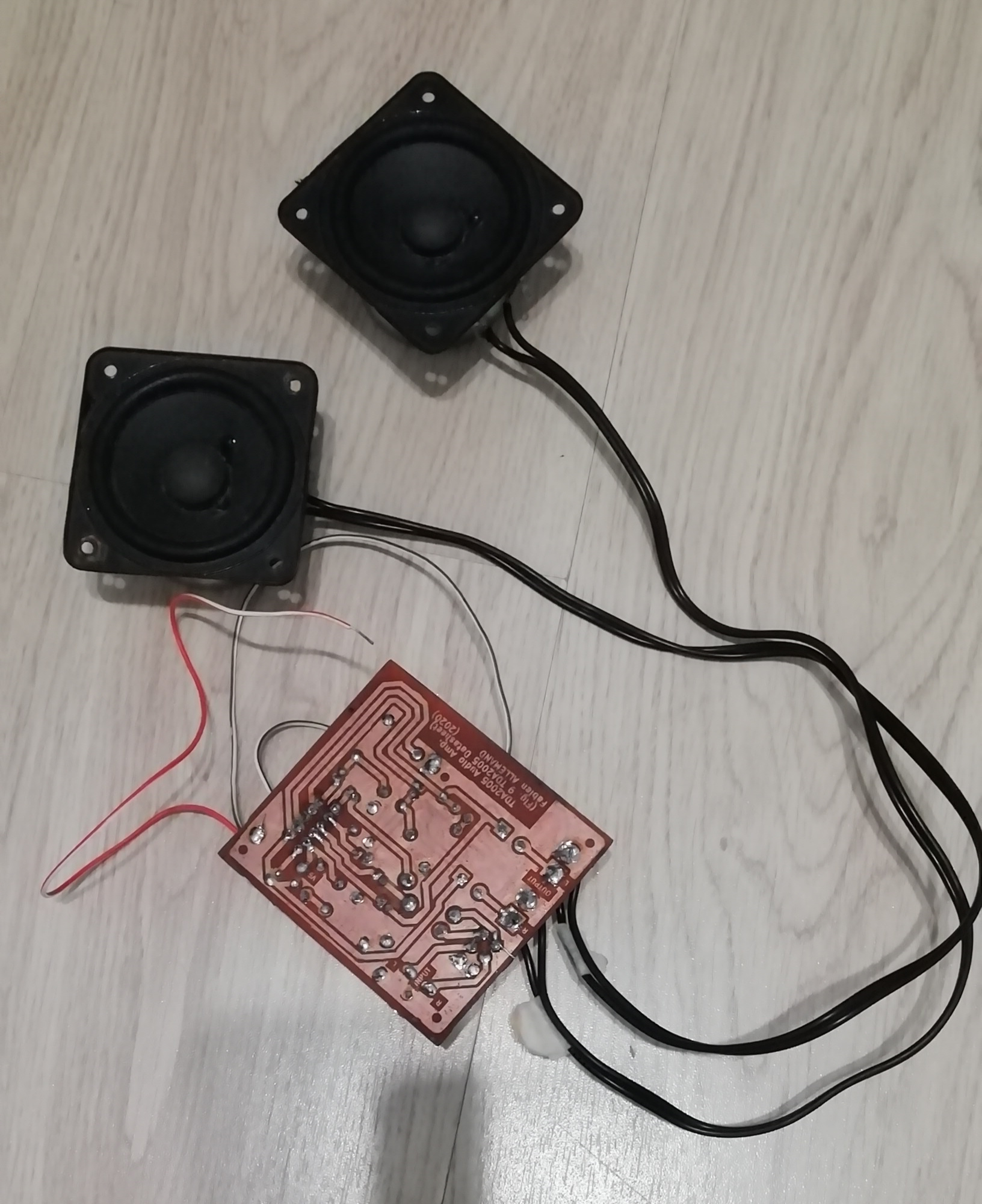
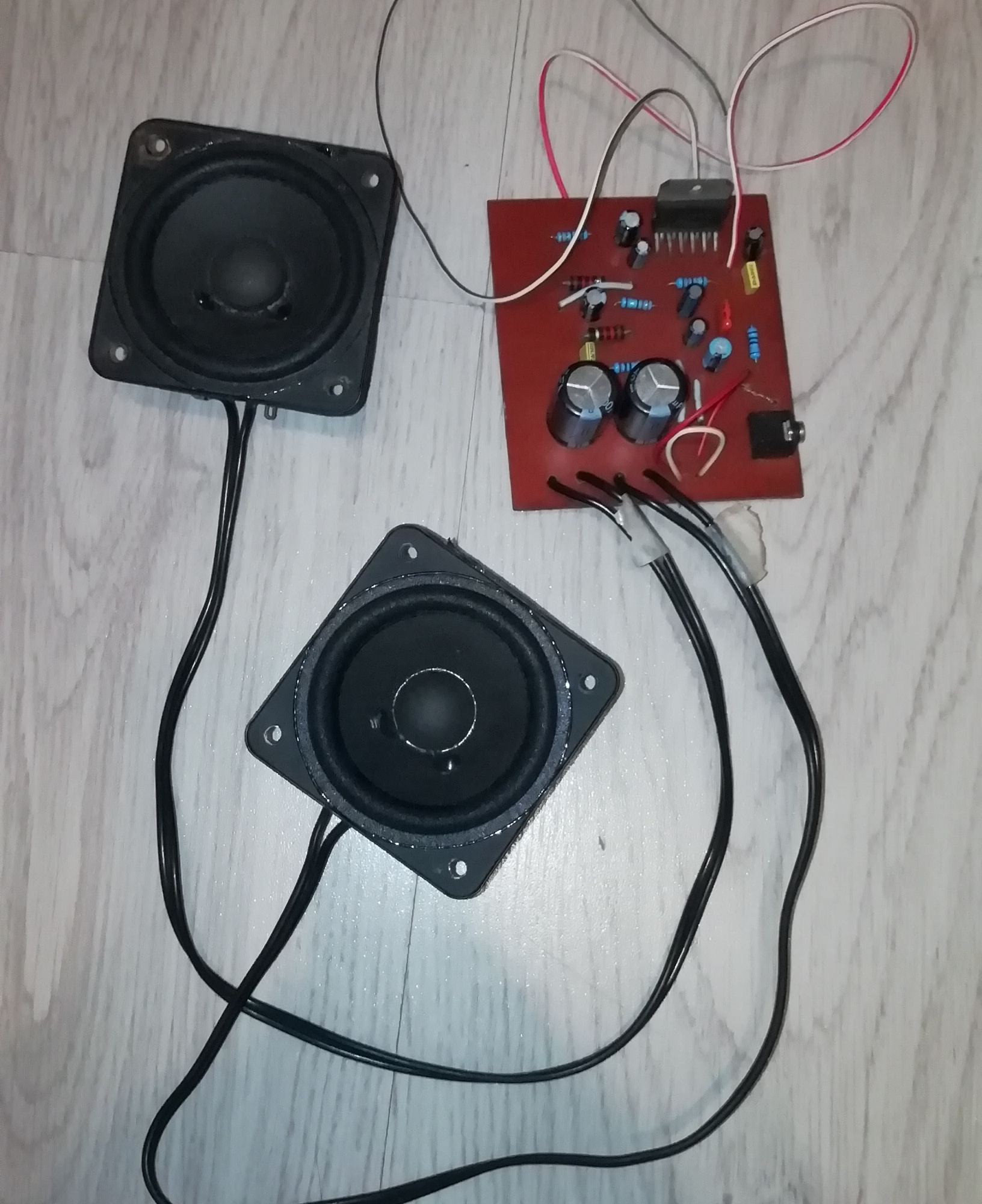
As I didn't know what was wrong with the board and I had other priorities (mainly studying 👨🏻🏫) I put the project aside for a while...
Industrial Revolution
...until I learnt how to use the Protomat S64 that was available at my new school's FabLab. I did not want to rush things again so I wanted to test the circuit on breadboards. Due to the specific pin layout of the amplifier IC I had to create a custom PCB to test everything.
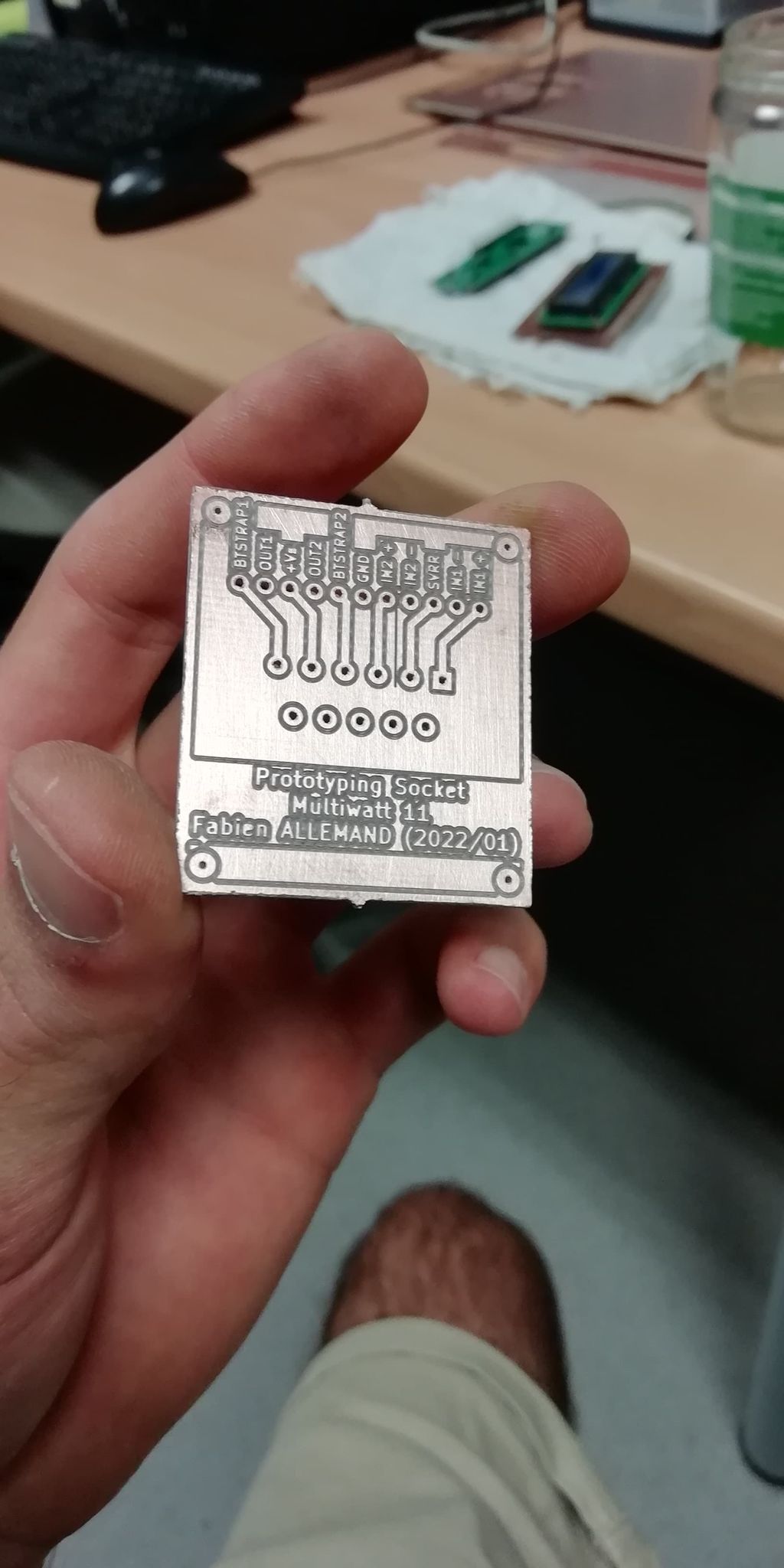
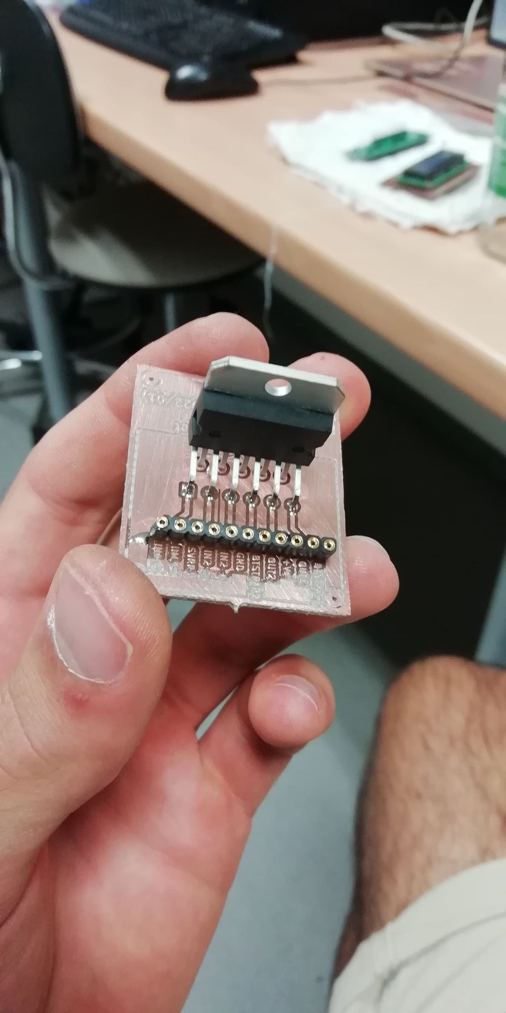
Then I re-created the circuit on the breadboard and... 🎶
Another Custom PCB
Without hesitation I fired up KiCAD, designed the PCB and headed to the FabLab to engrave it. That was really easy and... oh... 🤭
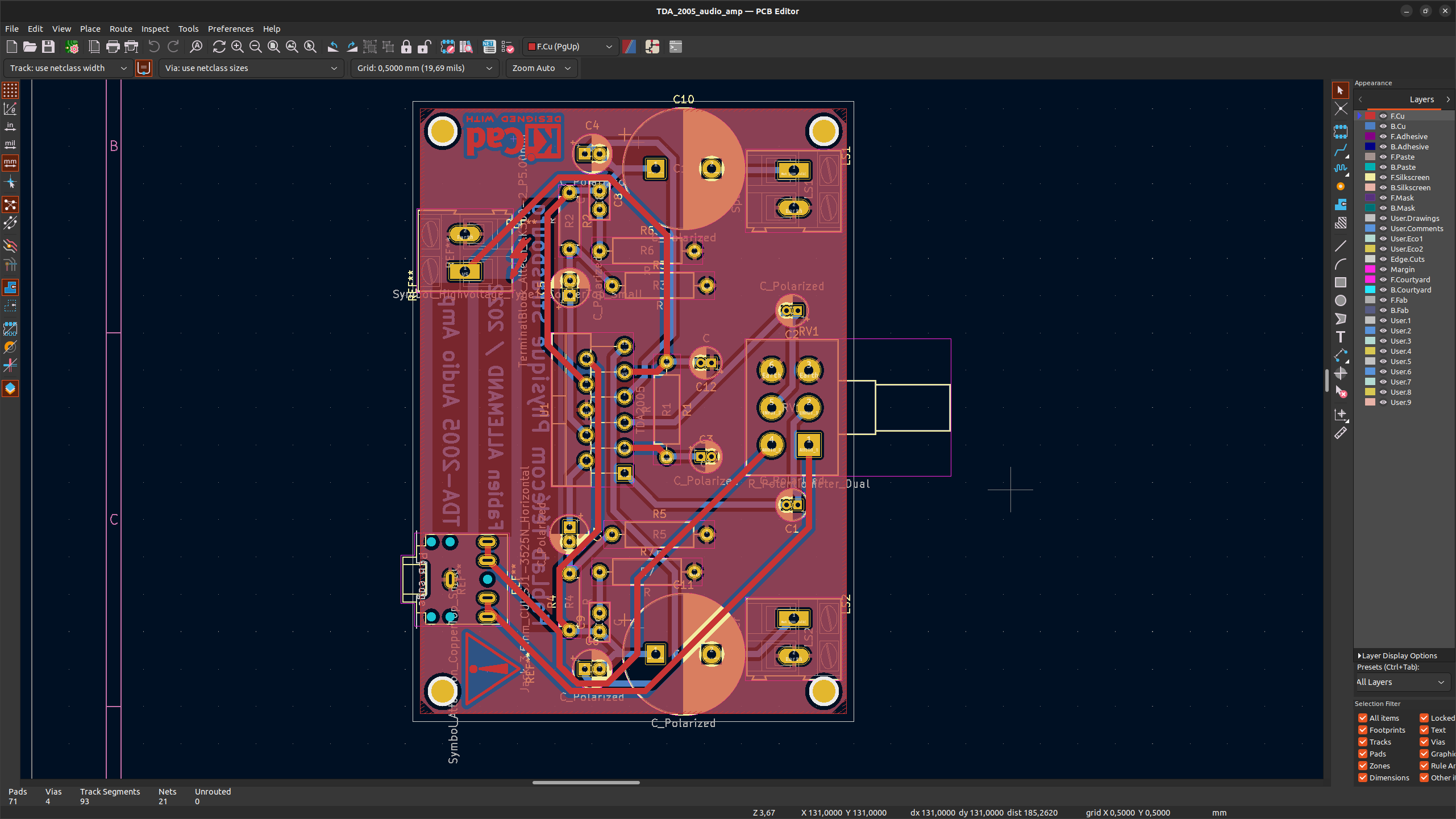
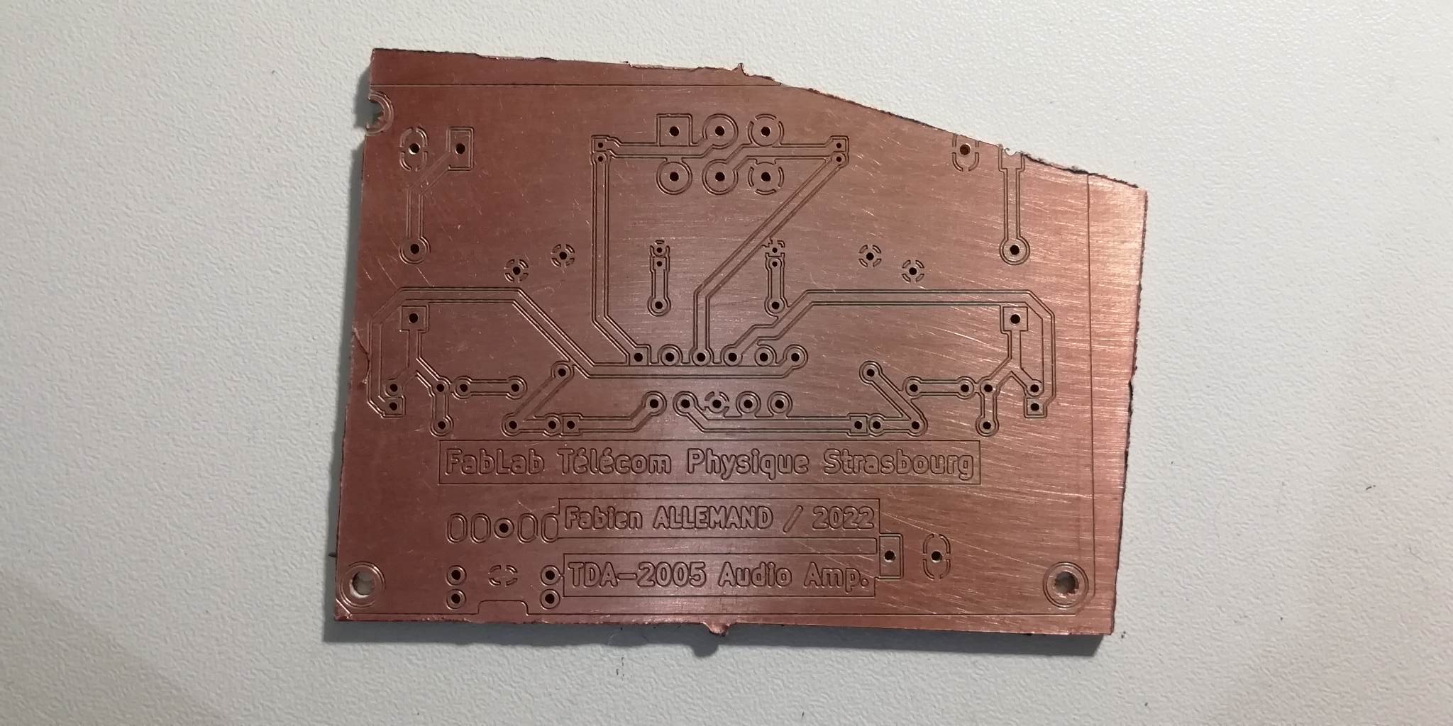
The project was put on stand by until the engraving machine was repaired... but as soon as it started working properly I rushed to the FabLab once again and...HELL YEAH!! 🤘
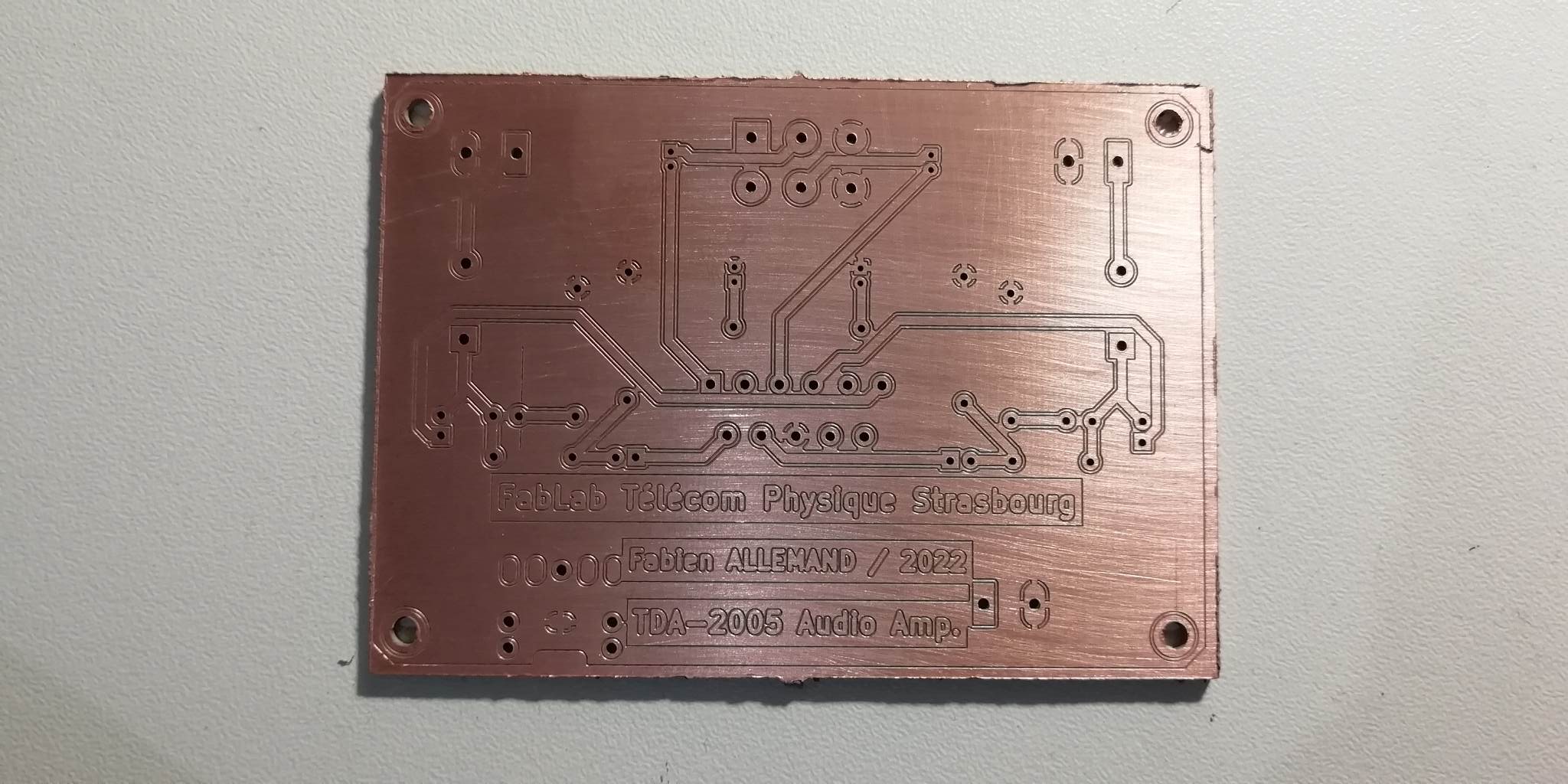
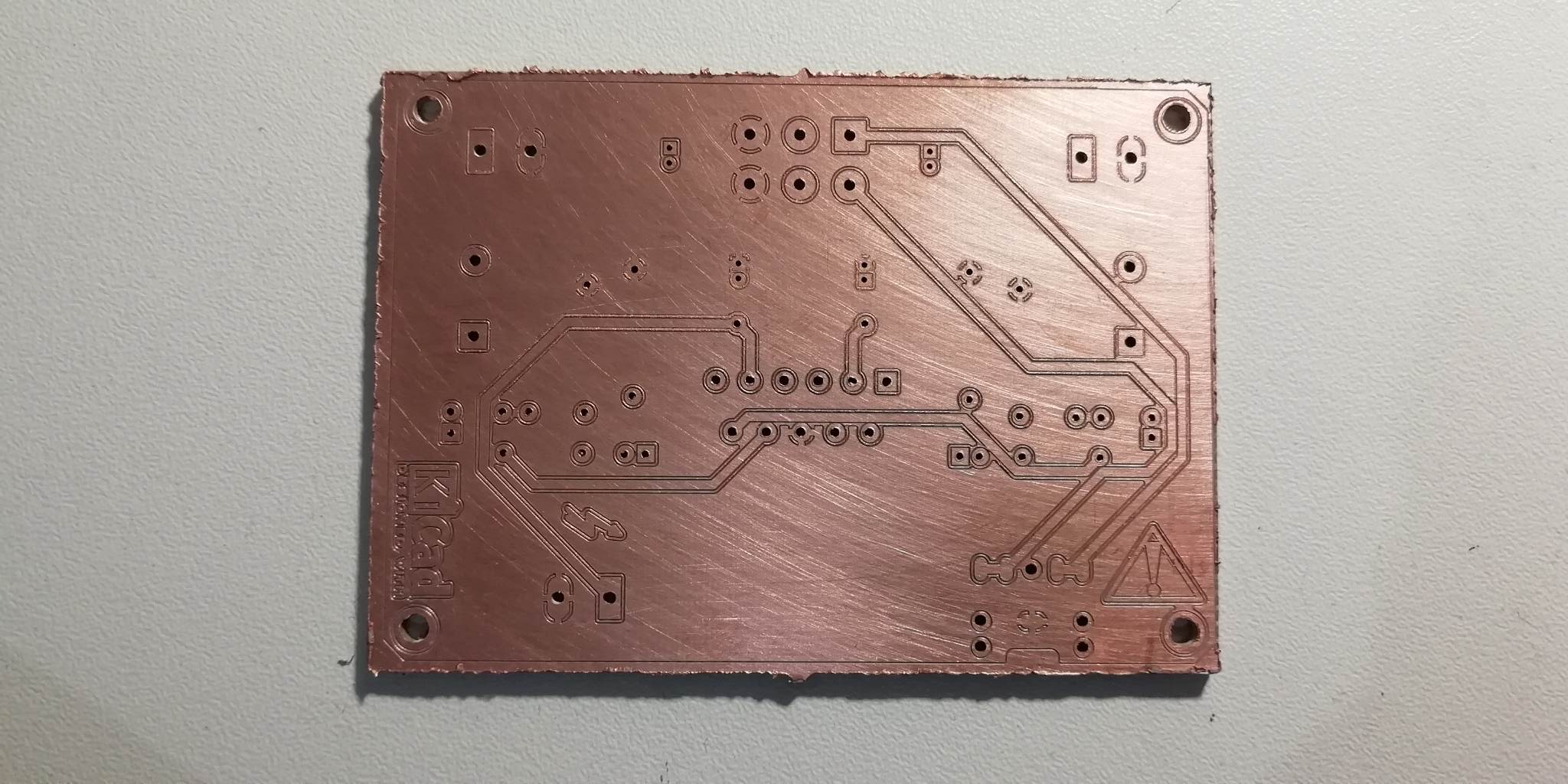
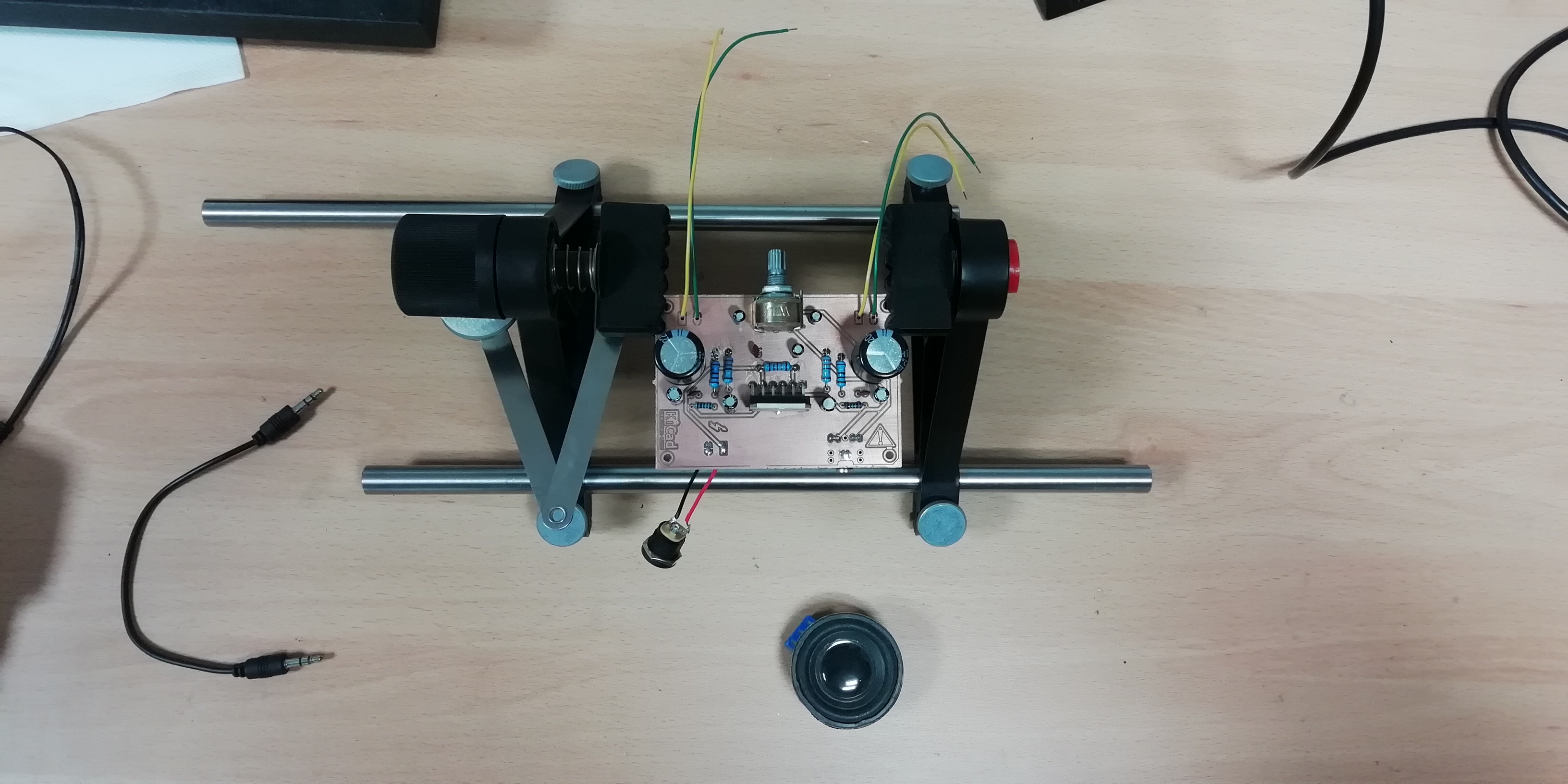
After a couple more hours working at the FabLab, I finally had a perfectly functionnal audio amplifier. Take a listen!! 🎸
Bluetooth
It was now time to go from the proof of concept to the actual product I originaly wanted to build: a speaker that I could use both with my computer and my phone.
Eventhough there are cheap and fairly usable Bluetooth board available online, adding Bluetooth functionnalities to the board is not necessarily easy.
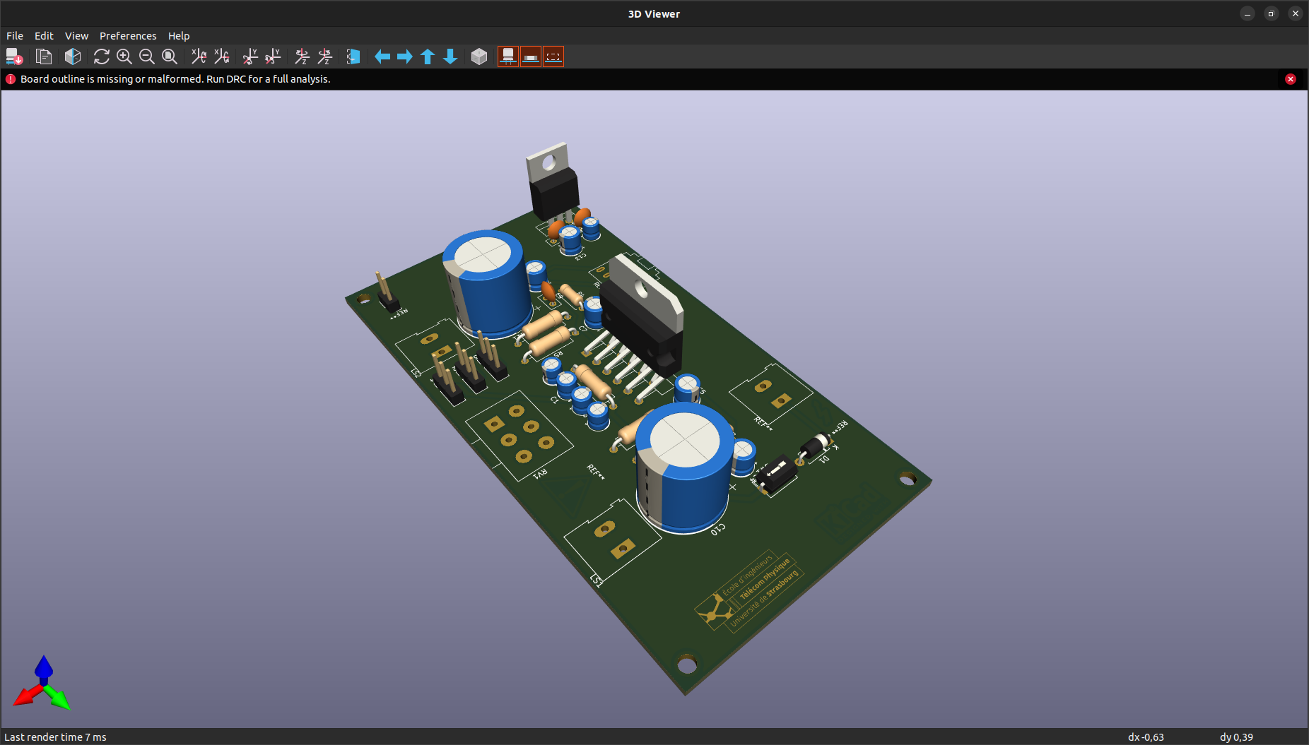
First, I had to use a voltage regulator to provide 5v to the Bluetooth module (note: I want to power the amplifier with more than 5v in order to drive the speakers). Then I had to had a button to shift between wired and Bluetooth mode.
But with all the experience accumulated during the three years of (non continuous) work on this project, I managed to make it work first try!! ⏯
Case